TA的每日心情 | 衰
2024-10-6 20:55 |
|---|
签到天数: 1 天 [LV.1]初来乍到
二级逆天
- 积分
- 1392
 
|
马上注册,结交更多好友,享用更多功能,让你轻松玩转社区
您需要 登录 才可以下载或查看,没有账号?立即注册
×
毫米波用户需要通过测试连续波来确认TI毫米波芯片发射射频信号的频率的准确性。用户对联参考设计板上进行发射天线的连续波测试有不同的测试要求。下面介绍三种不同测试场景的测试流程。
测试条件:
[li]硬件平台: MMWCAS-RF-EVM (revE)/MMWCAS-DSP-EVM[/li][li]PC软件: mmwave studio 3.00.00.14[/li][li]AWR2243 ES1.1的固件补丁: mmwave_dfp_02_02_03_01[/li][li]频谱分析仪[/li] 测试场景一
1. 测试要求:对级联板上每个AWR2243所有3根发射天线同时发射连续波的测试。
2. 测试流程:
[li]先在mmwave studio里运行下面的脚本进行所有4片AWR2243的参数配置。\mmwave_studio_03_00_00_14\mmWaveStudio\Scripts\Cascade\Cascade_ConfiguraTIon_ContStream.lua (测试脚本已经包含在mmwave studio里)[/li][li]然后运行下面的脚本。这个脚本会先使能芯片Slave 3的连续波发射,然后使能Slave2, Slave1,Master芯片。接着停止所有芯片的信号发射。最后保存相关ADC数据到SSD硬盘上,传送给PC。\mmwave_studio_03_00_00_14\mmWaveStudio\Scripts\Cascade\Cascade_Capture_ContStream.lua(测试脚本已经包含在mmwave studio里)[/li][li]通过频谱仪抓取和观测芯片的发射信号。[/li] 测试场景二
1. 测试要求:对级联板的AWR2243 主芯片(master)的单发射天线进行连续波的测试。
2. 测试流程:
以主芯片的TX0天线为例 (RadarDevice1)
a. 配置主芯片。
在mmwave studio里运行下面的脚本:
Cascade_ConfiguraTIon_ContStream_master_example.lua (具体内容见附录)
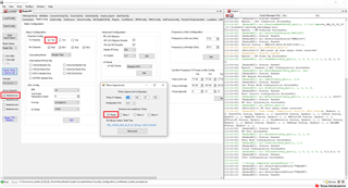
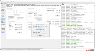
运行脚本后的mmwave studio界面信息如下:
b. 发射连续波。
运行下面的脚本:\mmwave_studio_03_00_00_14\mmWaveStudio\Scripts\Cascade\Cascade_Capture_ContStream.lua(测试脚本已经包含在mmwave studio里)
c. 通过频谱仪抓取和观测芯片的发射信号。
测试场景三
1. 测试要求:对级联板的AWR2243 从芯片(slave)的单发射天线进行连续波的测试。
2. 测试流程:
以slave2芯片的TX1天线为例 (RadarDevice3)
a. 配置从芯片。
在mmwave studio里运行下面的脚本:Cascade_ConfiguraTIon_ContStream_slave_example.lua(具体内容见附录)
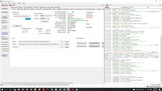
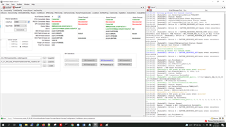
运行脚本后的mmwave studio界面信息如下:
b. 发射连续波。
运行下面的脚本:\mmwave_studio_03_00_00_14\mmWaveStudio\Scripts\Cascade\Cascade_Capture_ContStream.lua(测试脚本已经包含在mmwave studio里)
c. 通过频谱仪抓取和观测芯片的发射信号。
注意事项:
如果改变了AWR2243的ChanNAdcConfig_mult 参数(相对于上一次配置),用户必须对板子进行断电,再上电的操作。
常见问题:
1. 问题:如何使能、不使能主芯片或者是从芯片里的不同发射天线TX?
答案::用户需要修改配置参数的LUA脚本里ar1.ChanNAdcConfig_mult 函数的Tx0En/Tx1En/Tx2En 参数。关于这个函数的更多信息见下。对于Tx0En/Tx1En/Tx2En, 1表示使能,0表示不使能。
Int32 ar1.ChanNAdcConfig_mult(UInt16 RadarDeviceId, UInt16 Tx0En, UInt16 Tx1En, UInt16 Tx2En, UInt16 Rx0En, UInt16 Rx1En, UInt16 Rx2En, UInt32 Rx3En, Int32 BitsVal, UInt32 FmtVal, UInt32 IQSwap, UInt16 CasCadeMode) - Static device config API which defines configure both the Transmiter and Reciever channels of Radar device and also ADC data format output
_I_ UInt16 RadarDeviceId - Radar Device Id
_I_ UInt16 Tx0En - Tx0 channel
_I_ UInt16 Tx1En - Tx1 channel
_I_ UInt16 Tx2En - Tx2 channel
_I_ UInt16 Rx0En - Rx0 channel
_I_ UInt16 Rx1En - Rx1 channnel
_I_ UInt16 Rx2En - Rx2 channel
_I_ UInt32 Rx3En - Rx3 channel[b15:0] + (CascadePinOutCfg[b31:16] b16:ClkOutMasterDis, b17:SynOutMasterDis, b18:ClkOutSlaveEna, b19:SynOutSlaveEna, b20:IntLOMasterEna, b21:OSCClkOutMasterDis, b22:INTFRCMasterEna)
_I_ Int32 BitsVal - Number of ADC bits
_I_ UInt32 FmtVal - ADC output format[b15:0] + FullScaleReductionFactor[b31:16]
_I_ UInt32 IQSwap - ADC Mode
_I_ UInt16 CasCadeMode - CascadeMode(Single Chip: 0x0000, MultiChip Master:0x0001, MultiChip Slave:0x0002)
2. 问题:如何使能或者关闭级联板上不同的从芯片?
答案:用户需要修改配置参数的LUA里RadarDevice的设置。RadarDevice里dev1是主芯片,dev2、dev3、dev4是从芯片。
例如: RadarDevice = {1, 0, 1, 0} -- {dev1, dev2, dev3, dev4}, 1: Enable, 0: Disable
3. 问题:如何改变连续波的频率?
答案:用户需要修改配置参数的LUA里ar1.ContStrConfig_mult函数的startFreqConst参数值。
Int32 ar1.ContStrConfig_mult(UInt16 RadarDeviceId, Double startFreqConst,UInt16 digOutSampleRate, Char rxGain, Char hpfCornerFreq1, Char hpfCornerFreq2, UInt32 tx0OutPowerBackoffCode, UInt32 tx1OutPowerBackoffCode, UInt32 tx2OutPowerBackoffCode, UInt16 tx0PhaseShifter, UInt16 tx1PhaseShifter, UInt32 tx2PhaseShifter) - Continuous Streming Configuration API defines Configuration of the data path to transfer the captured ADC samples continuously without missing any sample to external Device(host)
_I_ UInt16 RadarDeviceId - Radar Device Id
_I_ Double startFreqConst - Start Frequency for each profile of chirp in GHz
_I_ UInt16 digOutSampleRate - ADC sampling rate for each profile in ksps
_I_ Char rxGain - Rx gain for each profile in dB
_I_ Char hpfCornerFreq1 - HPF1 corner frequency for each profile in KHz
_I_ Char hpfCornerFreq2 - HPF2 corner frequency for each profile in KHz
_I_ UInt32 tx0OutPowerBackoffCode - How much the trasmit power should be reduced from Max in Tx0 Channel
_I_ UInt32 tx1OutPowerBackoffCode - How much the trasmit power should be reduced from Max in Tx1 Channel
_I_ UInt32 tx2OutPowerBackoffCode - How much the trasmit power should be reduced from Max in Tx2 Channel
_I_ UInt16 tx0PhaseShifter - The additional phase shift to be introduced on Tx0 Channel
_I_ UInt16 tx1PhaseShifter - The additional phase shift to be introduced on Tx1 Channel
_I_ UInt32 tx2PhaseShifter - The additional phase shift to be introduced on Tx2 Channel(b0:15) + ForceSelect(b16) + VCOSelecct(b17))
附录:
1. Cascade_Configuration_ContStream_master_example.lua----------------------------------------User Constants--------------------------------------------dev_list = {1, 2, 4, 8} -- Device mapRadarDevice = {1, 0, 0, 0} -- {dev1, dev2, dev3, dev4}, 1: Enable, 0: Disablecascade_mode_list = {0, 2, 2, 2} -- 0: Single chip, 1: Master, 2: Slave //Chris: need to set in code directly-- F/W Download Path-- Uncomment the next line if you wish to pop-up a dialog box to select the firmware image file-- Otherwise, hardcode the path to the firmware metaimage below-- By default, the firmware filename is: xwr22xx_metaImage.bin-- metaImagePath = RSTD.BrowseForFile(RSTD.GetSettingsPath(), "bin", "Browse to .bin file")-- For 2243 ES1.1 devicesmetaImagePath = "C:\\ti\\mmwave_dfp_02_02_03_01\\firmware\\xwr22xx_metaImage.bin"-- For 2243 ES1.0 devices-- metaImagePath = "C:\\ti\\mmwave_dfp_02_02_00_02\\firmware\\xwr22xx_metaImage.bin"-- IP Address for the TDA2 Host Board-- Change this accordingly for your setupTDA_IPAddress = "192.168.33.180"-- Device map of all the devices to be enabled by TDA-- 1 - master ; 2- slave1 ; 4 - slave2 ; 8 - slave3deviceMapOverall = RadarDevice[1] + (RadarDevice[2]*2) + (RadarDevice[3]*4) + (RadarDevice[4]*8)deviceMapSlaves = (RadarDevice[2]*2) + (RadarDevice[3]*4) + (RadarDevice[4]*8)------------------------------ API Configuration -------------------------------------------------- 1. Connection to TDA. 2. Selecting Cascade/Single Chip. 3. Selecting 2-chip/4-chipWriteToLog("Setting up Studio for Cascade started..\n", "blue")if(0 == ar1.ConnectTDA(TDA_IPAddress, 5001, deviceMapOverall)) thenWriteToLog("ConnectTDA Successful\n", "green")elseWriteToLog("ConnectTDA Failed\n", "red")return -1endif(0 == ar1.selectCascadeMode(1)) thenWriteToLog("selectCascadeMode Successful\n", "green")elseWriteToLog("selectCascadeMode Failed\n", "red")return -1endWriteToLog("Setting up Studio for Cascade ended..\n", "blue")--Master Initialization-- SOP Mode Configurationif (0 == ar1.SOPControl_mult(1, 4)) thenWriteToLog("Master : SOP Reset Successful\n", "green")elseWriteToLog("Master : SOP Reset Failed\n", "red")return -1end-- SPI Connectif (0 == ar1.PowerOn_mult(1, 0, 1000, 0, 0)) thenWriteToLog("Master : SPI Connection Successful\n", "green")elseWriteToLog("Master : SPI Connection Failed\n", "red")return -1end-- Firmware Download. (SOP 4 - MetaImage)if (0 == ar1.DownloadBssFwOvSPI_mult(1, metaImagePath)) thenWriteToLog("Master : FW Download Successful\n", "green")elseWriteToLog("Master : FW Download Failed\n", "red")return -1end-- RF Power Upif (0 == ar1.RfEnable_mult(1)) thenWriteToLog("Master : RF Power Up Successful\n", "green")elseWriteToLog("Master : RF Power Up Failed\n", "red")return -1end-- Channel & ADC Configurationif (0 == ar1.ChanNAdcConfig_mult(1,1,0,0,1,1,1,1,2,1,0,0)) thenWriteToLog("Master : Channel & ADC Configuration Successful\n", "green")elseWriteToLog("Master : Channel & ADC Configuration Failed\n", "red")return -2end-- All devices together-- Including this depends on the type of board being used.-- LDO configurationif (0 == ar1.RfLdoBypassConfig_mult(deviceMapOverall, 3)) thenWriteToLog("LDO Bypass Successful\n", "green")elseWriteToLog("LDO Bypass failed\n", "red")return -2end-- Low Power Mode Configurationif (0 == ar1.LPModConfig_mult(deviceMapOverall,0, 0)) thenWriteToLog("Low Power Mode Configuration Successful\n", "green")elseWriteToLog("Low Power Mode Configuration failed\n", "red")return -2end-- Miscellaneous Control Configurationif (0 == ar1.SetMiscConfig_mult(deviceMapOverall, 1, 0, 0, 0)) thenWriteToLog("Misc Control Configuration Successful\n", "green")elseWriteToLog("Misc Control Configuration failed\n", "red")return -2end-- Edit this API to enable/disable the boot time calibration. Enabled by default.-- RF Init Calibration Configurationif (0 == ar1.RfInitCalibConfig_mult(deviceMapOverall, 1, 1, 1, 1, 1, 1, 1, 65537)) thenWriteToLog("RF Init Calibration Successful\n", "green")elseWriteToLog("RF Init Calibration failed\n", "red")return -2end-- RF Initif (0 == ar1.RfInit_mult(deviceMapOverall)) thenWriteToLog("RF Init Successful\n", "green")elseWriteToLog("RF Init failed\n", "red")return -2end---------------------------Data Configuration------------------------------------ Data path Configurationif (0 == ar1.DataPathConfig_mult(deviceMapOverall, 0, 1, 0)) thenWriteToLog("Data Path Configuration Successful\n", "green")elseWriteToLog("Data Path Configuration failed\n", "red")return -3end-- Clock Configurationif (0 == ar1.LvdsClkConfig_mult(deviceMapOverall, 1, 1)) thenWriteToLog("Clock Configuration Successful\n", "green")elseWriteToLog("Clock Configuration failed\n", "red")return -3end-- CSI2 Configurationif (0 == ar1.CSI2LaneConfig_mult(deviceMapOverall, 1, 0, 2, 0, 4, 0, 5, 0, 3, 0, 0)) thenWriteToLog("CSI2 Configuration Successful\n", "green")elseWriteToLog("CSI2 Configuration failed\n", "red")return -3end2. Cascade_Configuration_ContStream_slave_example.lua----------------------------------------User Constants--------------------------------------------dev_list = {1, 2, 4, 8} -- Device mapRadarDevice = {1, 0, 1, 0} -- {dev1, dev2, dev3, dev4}, 1: Enable, 0: Disablecascade_mode_list = {1, 2, 2, 2} -- 0: Single chip, 1: Master, 2: Slave-- F/W Download Path-- Uncomment the next line if you wish to pop-up a dialog box to select the firmware image file-- Otherwise, hardcode the path to the firmware metaimage below-- By default, the firmware filename is: xwr22xx_metaImage.bin-- metaImagePath = RSTD.BrowseForFile(RSTD.GetSettingsPath(), "bin", "Browse to .bin file")-- For 2243 ES1.1 devicesmetaImagePath = "C:\\ti\\mmwave_dfp_02_02_03_01\\firmware\\xwr22xx_metaImage.bin"-- For 2243 ES1.0 devices-- metaImagePath = "C:\\ti\\mmwave_dfp_02_02_00_02\\firmware\\xwr22xx_metaImage.bin"-- IP Address for the TDA2 Host Board-- Change this accordingly for your setupTDA_IPAddress = "192.168.33.180"-- Device map of all the devices to be enabled by TDA-- 1 - master ; 2- slave1 ; 4 - slave2 ; 8 - slave3deviceMapOverall = RadarDevice[1] + (RadarDevice[2]*2) + (RadarDevice[3]*4) + (RadarDevice[4]*8)deviceMapSlaves = (RadarDevice[2]*2) + (RadarDevice[3]*4) + (RadarDevice[4]*8)------------------------------ API Configuration -------------------------------------------------- 1. Connection to TDA. 2. Selecting Cascade/Single Chip. 3. Selecting 2-chip/4-chipWriteToLog("Setting up Studio for Cascade started..\n", "blue")if(0 == ar1.ConnectTDA(TDA_IPAddress, 5001, deviceMapOverall)) thenWriteToLog("ConnectTDA Successful\n", "green")elseWriteToLog("ConnectTDA Failed\n", "red")return -1endif(0 == ar1.selectCascadeMode(1)) thenWriteToLog("selectCascadeMode Successful\n", "green")elseWriteToLog("selectCascadeMode Failed\n", "red")return -1endWriteToLog("Setting up Studio for Cascade ended..\n", "blue")--Master Initialization-- SOP Mode Configurationif (0 == ar1.SOPControl_mult(1, 4)) thenWriteToLog("Master : SOP Reset Successful\n", "green")elseWriteToLog("Master : SOP Reset Failed\n", "red")return -1end-- SPI Connectif (0 == ar1.PowerOn_mult(1, 0, 1000, 0, 0)) thenWriteToLog("Master : SPI Connection Successful\n", "green")elseWriteToLog("Master : SPI Connection Failed\n", "red")return -1end-- Firmware Download. (SOP 4 - MetaImage)if (0 == ar1.DownloadBssFwOvSPI_mult(1, metaImagePath)) thenWriteToLog("Master : FW Download Successful\n", "green")elseWriteToLog("Master : FW Download Failed\n", "red")return -1end-- RF Power Upif (0 == ar1.RfEnable_mult(1)) thenWriteToLog("Master : RF Power Up Successful\n", "green")elseWriteToLog("Master : RF Power Up Failed\n", "red")return -1end-- Channel & ADC Configurationif (0 == ar1.ChanNAdcConfig_mult(1,0,0,0,1,1,1,1,2,1,0,1)) thenWriteToLog("Master : Channel & ADC Configuration Successful\n", "green")elseWriteToLog("Master : Channel & ADC Configuration Failed\n", "red")return -2end-- Slaves Initializationfor i=2,table.getn(RadarDevice) dolocal status = 0if ((RadarDevice[1]==1) and (RadarDevice==1)) then-- SOP Mode Configurationif (0 == ar1.SOPControl_mult(dev_list, 4)) thenWriteToLog("Device "..i.." : SOP Reset Successful\n", "green")elseWriteToLog("Device "..i.." : SOP Reset Failed\n", "red")return -1end-- SPI Connectif (0 == ar1.AddDevice(dev_list)) thenWriteToLog("Device "..i.." : SPI Connection Successful\n", "green")elseWriteToLog("Device "..i.." : SPI Connection Failed\n", "red")return -1endendend-- Firmware Download. (SOP 4 - MetaImage)if (0 == ar1.DownloadBssFwOvSPI_mult(deviceMapSlaves, metaImagePath)) thenWriteToLog("Slaves : FW Download Successful\n", "green")elseWriteToLog("Slaves : FW Download Failed\n", "red")return -1end-- RF Power Upif (0 == ar1.RfEnable_mult(deviceMapSlaves)) thenWriteToLog("Slaves : RF Power Up Successful\n", "green")elseWriteToLog("Slaves : RF Power Up Failed\n", "red")return -1end-- Channel & ADC Configurationif (0 == ar1.ChanNAdcConfig_mult(deviceMapSlaves,0,1,0,1,1,1,1,2,1,0,2)) thenWriteToLog("Slaves : Channel & ADC Configuration Successful\n", "green")elseWriteToLog("Slaves : Channel & ADC Configuration Failed\n", "red")return -2end-- All devices together-- Including this depends on the type of board being used.-- LDO configurationif (0 == ar1.RfLdoBypassConfig_mult(deviceMapOverall, 3)) thenWriteToLog("LDO Bypass Successful\n", "green")elseWriteToLog("LDO Bypass failed\n", "red")return -2end-- Low Power Mode Configurationif (0 == ar1.LPModConfig_mult(deviceMapOverall,0, 0)) thenWriteToLog("Low Power Mode Configuration Successful\n", "green")elseWriteToLog("Low Power Mode Configuration failed\n", "red")return -2end-- Miscellaneous Control Configurationif (0 == ar1.SetMiscConfig_mult(deviceMapOverall, 1, 0, 0, 0)) thenWriteToLog("Misc Control Configuration Successful\n", "green")elseWriteToLog("Misc Control Configuration failed\n", "red")return -2end-- Edit this API to enable/disable the boot time calibration. Enabled by default.-- RF Init Calibration Configurationif (0 == ar1.RfInitCalibConfig_mult(deviceMapOverall, 1, 1, 1, 1, 1, 1, 1, 65537)) thenWriteToLog("RF Init Calibration Successful\n", "green")elseWriteToLog("RF Init Calibration failed\n", "red")return -2end-- RF Initif (0 == ar1.RfInit_mult(deviceMapOverall)) thenWriteToLog("RF Init Successful\n", "green")elseWriteToLog("RF Init failed\n", "red")return -2end---------------------------Data Configuration------------------------------------ Data path Configurationif (0 == ar1.DataPathConfig_mult(deviceMapOverall, 0, 1, 0)) thenWriteToLog("Data Path Configuration Successful\n", "green")elseWriteToLog("Data Path Configuration failed\n", "red")return -3end-- Clock Configurationif (0 == ar1.LvdsClkConfig_mult(deviceMapOverall, 1, 1)) thenWriteToLog("Clock Configuration Successful\n", "green")elseWriteToLog("Clock Configuration failed\n", "red")return -3end-- CSI2 Configurationif (0 == ar1.CSI2LaneConfig_mult(deviceMapOverall, 1, 0, 2, 0, 4, 0, 5, 0, 3, 0, 0)) thenWriteToLog("CSI2 Configuration Successful\n", "green")elseWriteToLog("CSI2 Configuration failed\n", "red")return -3end |
|

 再发某公司的PADS格式 PCB封装库全套共享
 Allegro超强最全模仿PADS快捷键实现Z切换层
 RK3576图片展示
 xilinx XC7Z010/020-TLZ7x-EasyEVM-A3
 TL138_1808_6748F-EVM-A2_16D2
 CH7026B-RGB转VGA
 120W 电源板PCB文件共享
 allegro羊皮卷
 60N10 N型沟道MOSFET产品概述
 高抗干扰10按键触摸/触控感应芯片VK3610I S
 CCDCMOS图像传感器基础与应用.pdf
 HyperLynX仿真与PCB设计[PCB工程师从入门到
 无线连接测试仪的技术原理和应用场景
 信号完整性与电源完整性分析(第3版).pdf

 发表于 2021-11-11 10:38:03


")
")